AT-2040 Portable Vibration Calibrator
Gen-2 Smart Shaker with Real-Time Sensitivity Display
Lab-grade accuracy in the field. Four operating modes, built-in sensitivity display, data logging, and long-life LiFePO4 battery — all in one rugged portable unit.
Four operating modes — one complete verification workflow
Each mode supports a specific step in sensor testing, system validation, and reliability training.

Vibration Output
Manual control of frequency and amplitude with live feedback on sensitivity, bias voltage, and waveform distortion.
Bearing Defect
Generate realistic inner race, outer race, and ball pass faults for technician training and diagnostic system validation.
Sensor Test
Automated multi-point testing with real-time sensitivity display and onboard data logging.
Sensor Simulation
Simulate accelerometer, velocity, and proximity probe signals to validate monitoring systems without applying physical vibration.
Together, these modes allow technicians to verify sensors, validate systems, and build confidence in vibration data — from initial setup through advanced diagnostics.
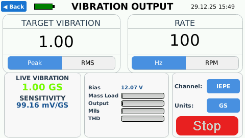
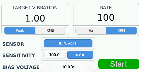
Vibration Output
Vibration Output mode is used for manual vibration testing with real-time measurement of actual shaker output. Rather than assuming vibration levels based on drive settings, the AT-2040 continuously measures true mechanical motion using its internal reference sensor.
In this mode, the user manually sets vibration frequency and amplitude while the system provides live feedback on measured vibration level, sensor sensitivity, displacement, harmonic distortion, and amplifier load. This closed-loop approach allows users to confidently verify sensor performance and system response under real mechanical excitation.
Vibration Output mode is particularly useful for manual verification, troubleshooting, and exploratory testing, where direct control and immediate feedback are required before transitioning to automated test routines.
Supported sensors.
- IEPE accelerometers
- Charge-mode accelerometers
- Voltage output accelerometers (AC/ DC , MEMS)
- Velocity Sensors (piezo & moving coil)
- Proximity probes (eddy-current displacement)
- 4-20mA vibration transmitters
What this mode enables
- Manually excite sensors with controlled frequency and amplitude
- Measure true vibration output using an internal reference accelerometer
- View live sensitivity, displacement, amplifier load, and harmonic distortion.
- Verify sensors, cabling, and monitoring systems without automation.
- Operate with or without a connected sensor (shaker-only mode)
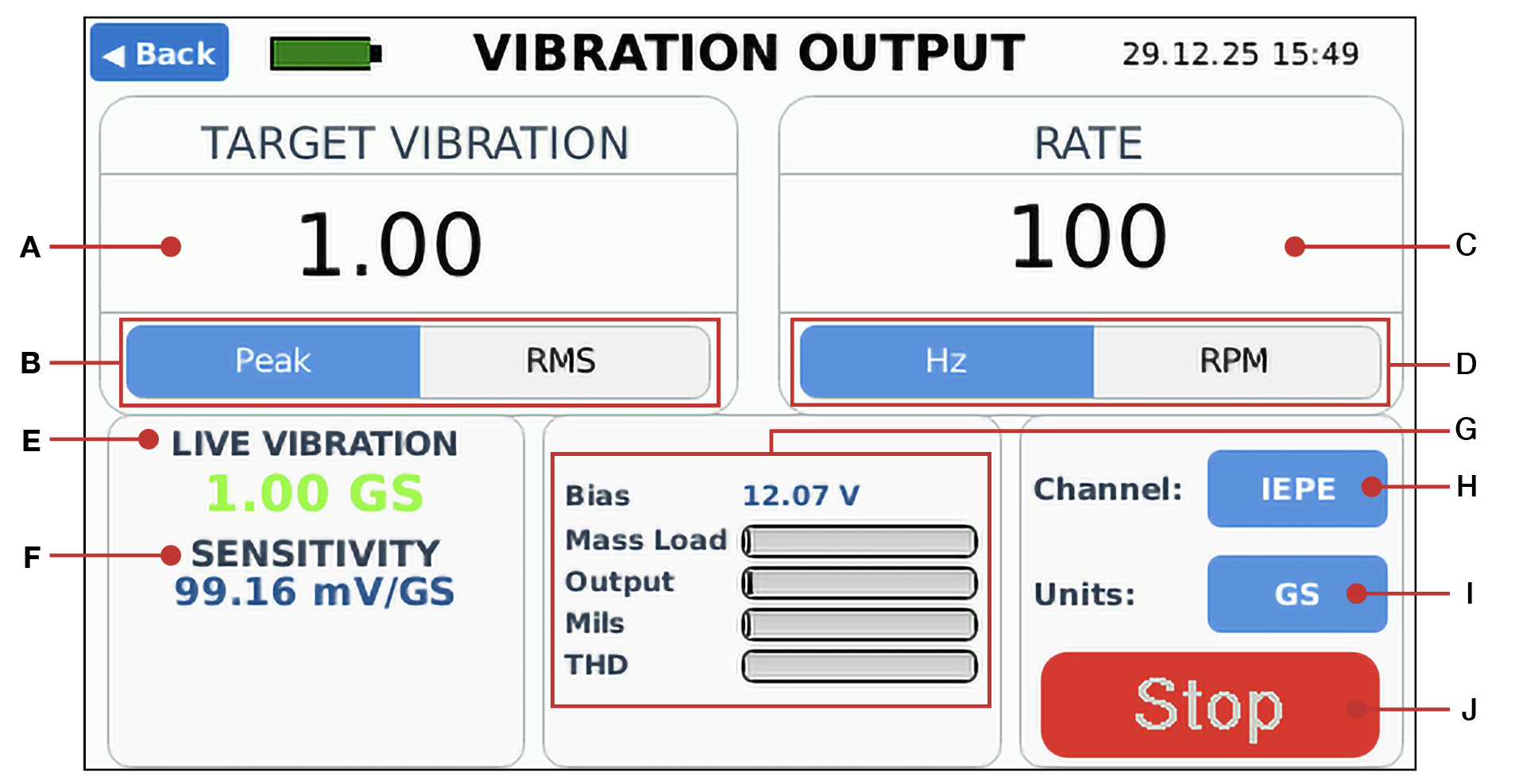
Screen Reference
| Ref | Control | Description |
|---|---|---|
|
A |
Target Vibration |
Sets the vibration amplitude. |
|
B |
Peak/RMS Toggle |
Switches the vibration measurement between Peak and RMS modes |
|
C |
Rate |
Sets the vibration frequency or RPM |
|
D |
Hz / RPM Toggle |
Switches the rate display between frequency (Hz) and speed (RPM). |
|
E |
Live Vibration |
Displays the actual vibration output of the shaker |
|
F |
Sensitivity |
Shows the measured sensitivity of the connected sensor. |
|
G |
Output Status |
Displays bias or gap voltage, mass load, amplifier output level, and total harmonic distortion in real time. |
|
H |
Channel |
Selects the active sensor input channel. |
|
I |
Units |
Selects vibration units for live vibration and sensitivity display. |
|
J |
Start/Stop |
Starts or stops the vibration output test. |
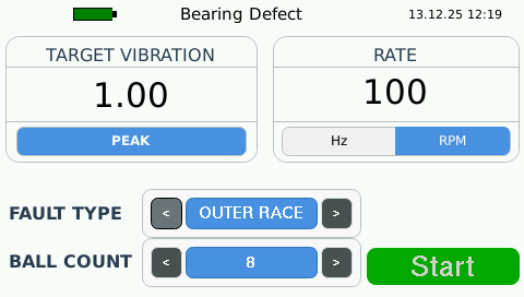
Bearing Fault Simulation & Verification
The AT-2040 Gen 2 includes an integrated bearing fault pulse generator that produces realistic, repeatable bearing defect waveforms for condition monitoring system validation, alarm testing, and technician training.
Fault simulation capabilities
- Inner race, outer race, ball, and cage defect simulation
- Adjustable defect frequency and repetition rate
- Stable, repeatable pulse generation
- No damaged bearings or rotating machinery required
When to use this mode
This mode is used when validating bearing fault detection logic, alarm thresholds, and analysis techniques, rather than overall vibration level accuracy.
Why This Matters
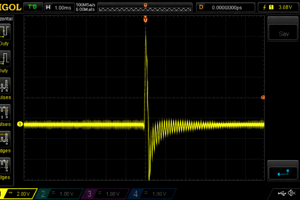
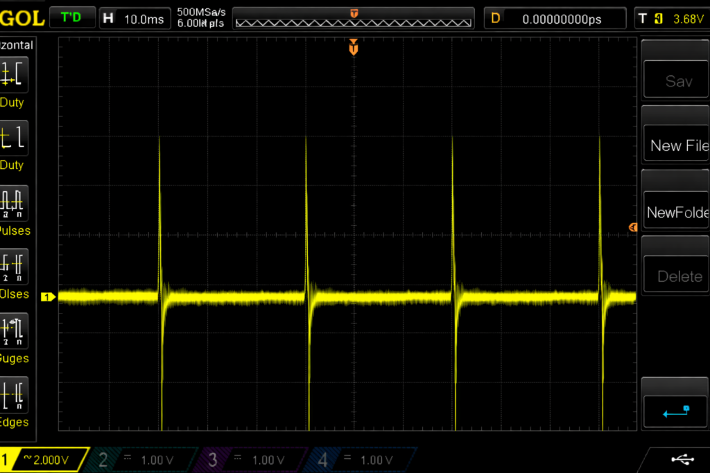
Bearing Fault Waveform Behavior
The oscilloscope captures shown below illustrate the waveform characteristics produced by the AT-2040 Gen 2 bearing fault simulation.
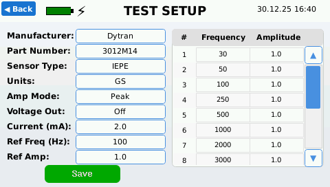
Automatic Sensor & Proximity Probe Testing
Fully automated vibration and proximity verification — no manual setup, no spreadsheets, no PC software.
The AT-2040 automatically controls frequency and amplitude, measures sensor response in real time, and calculates sensitivity across defined test points — all directly on the instrument.
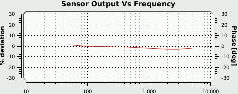
The Sensor Test mode automates vibration sensor calibration by controlling output levels, measuring response, and calculating sensitivity across defined test points.
This mode reduces setup time and eliminates manual calculations, providing consistent, repeatable results suitable for both field verification and laboratory use.
- Automatic frequency and amplitude control
- Live sensitivity, bias, and deviation measurement
- Repeatable test points with no user input
- Cert-ready results for calibration documentation
- Designed for both field and laboratory workflows
Not limited to accelerometers
The same automatic test framework also supports proximity probe dynamic testing, including controlled amplitude sweeps and sensitivity verification — using the same on-device workflow with no external software.
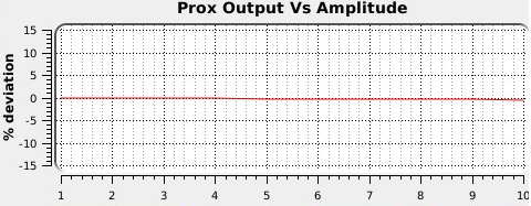
Learn more about automatic proximity probe testing →
In addition to automated testing, the AT-2040 also includes built-in simulation capabilities.
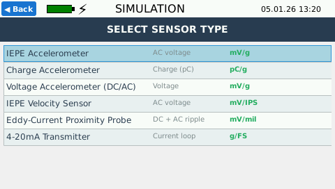
Built-in Sensor & Signal Simulation
Simulate accelerometers, proximity probes, and vibration signals without external hardware.
- Simulate accelerometers and proximity probes
- Generate repeatable vibration signals for system checks
- Ideal for training, troubleshooting, and validation
- On-device operation with no external equipment
Optional Accessories
Proximity Probe Adapter Kit
- Proximity Probe Driver Power Sourced Directly from AT2040 Battery
- Both AC and DC voltages shown on screen.
MEMS Adapter
- Analog MEMS adapter for sensitivity readings of Piezoresistive and Variable Capacitance sensors of all major manufacturers.
- 1x and 10 signal conditioners included.
- Power Sourced Directly from AT2040 Battery
- This simple and effective design supports single and double ended sensors.
Specifications
| Feature | Details |
|---|---|
|
Calibration Standard |
A2LA Accredited ISO/IEC 17025:2017, NIST Traceable |
|
Frequency Range |
Vibration: 5 Hz – 10 kHz Simulation: 1 Hz – 11 kHz |
|
Operating Modes |
Vibration Output, Bearing Defect, Sensor Test, Sensor Simulation |
|
Display |
Real-time Sensitivity, Live Vibration, Bias/Gap Voltage, Distortion |
|
Battery |
12V 6Ah LiFePO4 ~5000 cycles |
|
Power |
Built-in smart charger, 100-240V |
|
Supported Sensors |
IEPE, Charge, Voltage, Velocity, Proximity Probes, 4-20 mA, MEMS |
|
Data Output |
Onboard logging + PDF certificate generation, CSV export |
|
Connectivity |
Wi-Fi (remote VNC control) |
Downloads


Type
Portable Vibration Calibrator / Shaker table / Accelerometer and Proximity Probe Signal Generator / Bearing Fault Simulator
Frequency Range
Simulation Signal: 1 – 11k Hz
Vibration Signal
Variable frequency and amplitude
Test Types
Manual sensitivity, Sensor simulation, Automatic sweep, and Certification.
Supported Sensor Input Types
Accelerometer:
Voltage
IEPE
Charge
Velocity
Coil
Piezoresistive (MEMS Adapter Required)
Variable Capacitance (MEMS Adapter Required)
4-20mA transmitters
Proximity probes (Direct input for AC and DC readings) (Axial / Radial)
Sensor Simulation Output
Charge signal (variable frequency and amplitude)
4-20ma (adjustable) Proximity probes (adjustable)
Power Output
-24 volt power to power proximity probe drivers
+24 volt power for 4-20ma sensors and transmitter type drivers
Certifications and Agency Requirements
A2LA Accredited Calibration
ISO/IEC 17025:2017
R205
NIST Traceable
LVD: EN61010-1: 2010
EMC: EN61326-1
CE Mark: Product Specific Standard
RoHS
Request pricing and availability.

