
Features
LiFeP04 Battery
Functionality
Applications
Simulator
Features
- A2LA Accreditation ISO/IEC 17025:2017*
- Quartz Reference Accelerometer
- Calibrated back to back with laser calibrated primary reference for increased accuracy.
- Simulation Mode.*
- Digital closed loop control.
- Digital Electronics
- 100-240v power with standard plug receptacle and built in charger.
- Custom PC Software included to setup Full-Automatic Test Mode
- Built in Charge Converter
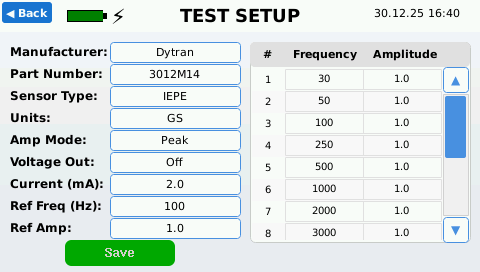
- IEPE, Voltage, charge (piezoelectric), 4-20mA, and proximity probe sensitivity readings
- Adjustable current and voltage
- Automatic PDF certificate generation tailored to your custom specifications
- Export Data to CSV.
- Connect to a PC through Wi-Fi and control the device from a remote location with Google Chrome’s built in VNC viewer
LiFeP04 Battery
The LiFeP04 battery outperforms Lead-Acid in almost every measurable way.
- Longer Life Span of (5-10) years vs lead acid (3-5) years.
- More cycle lifes – LiFeP04 batteries last 1,000 to 3,000 charge and discharge cycles compared to lead acid 200-1,000.
- LifePo4 batteries are more environmental friendly than Lead Acid
- Lighter weight. LiFeP04 battery cuts out 3lbs in AT2040 shaker vs lead acid.
- Very Safe to use and does not need a dangerous good exemption for air transport like Lead-Acid Batteries.
- Significantly faster charging time vs lead-acid batteries
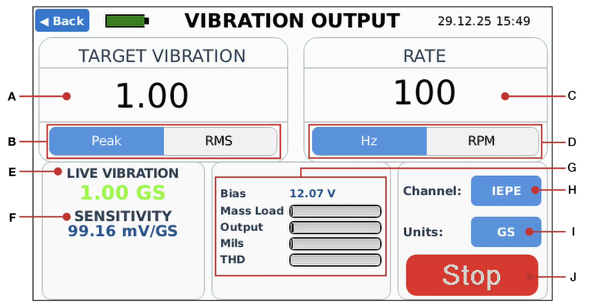
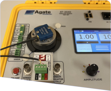
Functionality
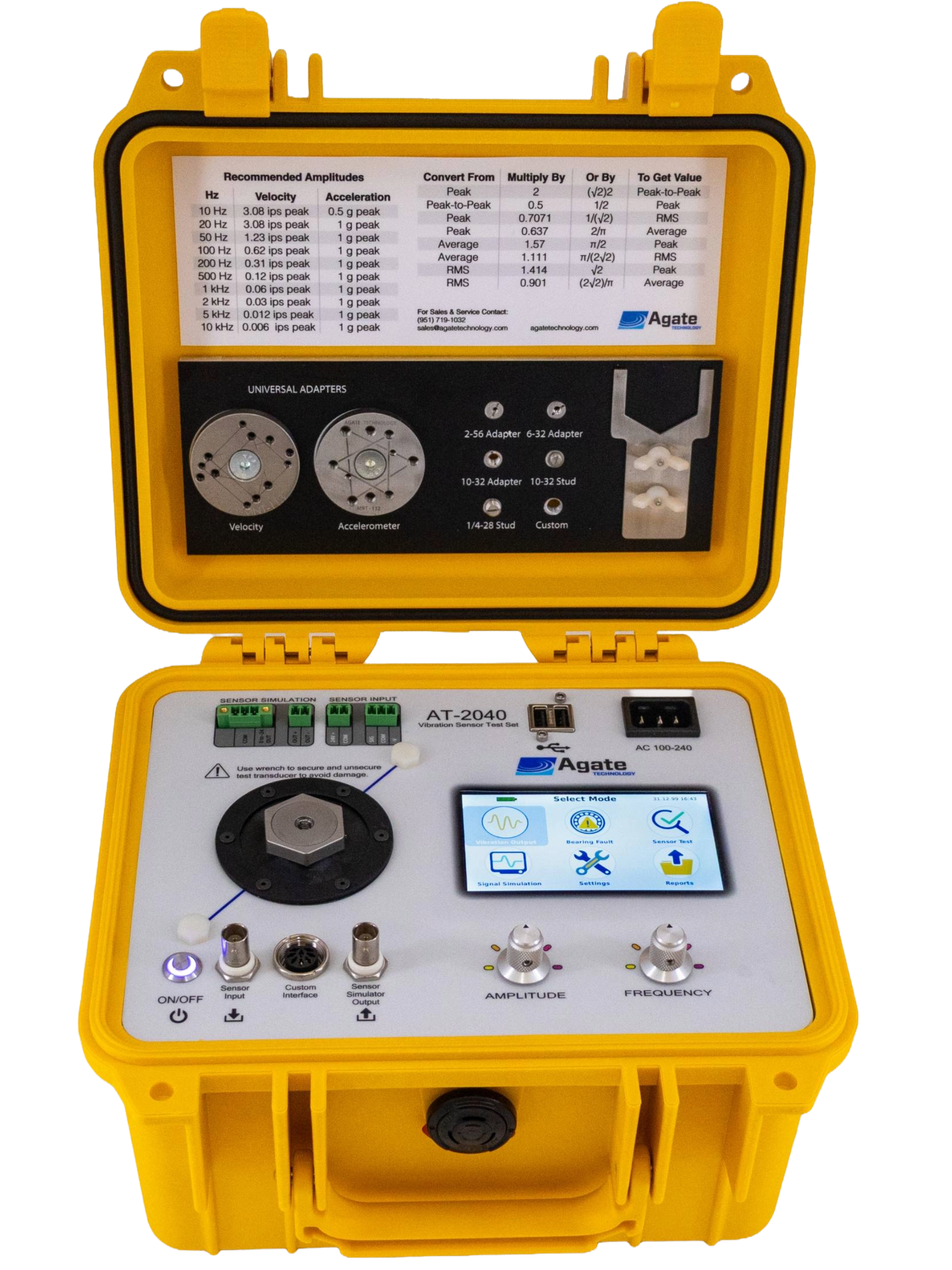
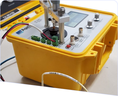
The AT2040 Portable Vibration Calibrator is packed with features and functionality. Comprehensive and user-friendly software tools help operators quickly identify and address issues in their vibration system setups
- Create calibration certificates for vibration instruments.
- Test all types of vibration sensors and transducers from a variety of accelerometer and eddy current probe manufacturers.
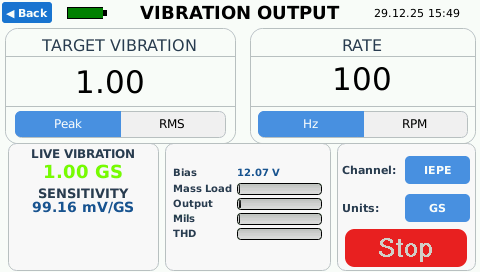
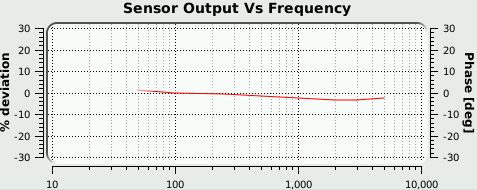
- Provides a closed loop controlled reference signal from 5 Hz to 10,000Hz for testing over a wide frequency range.
Applications
The AT2040 has many applications including:
- Cabling and wiring troubleshooting
- Vibration signal simulation—accelerometers and velocity probes
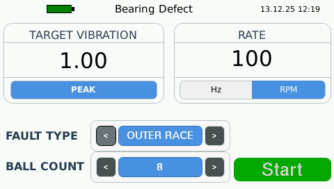
- Machinery speed signal simulation
-
Calibration for:
- Accelerometers
- Proximity probes and drivers
- Monitoring systems
- Avionics equipment
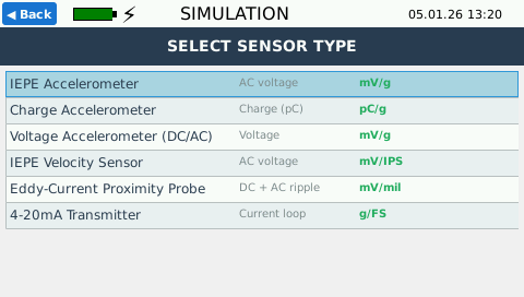
Simulator
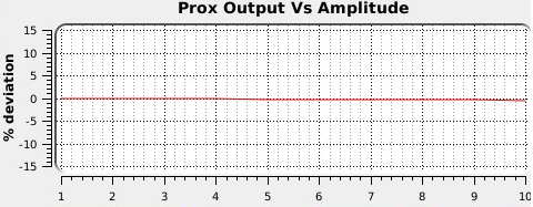
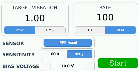
AT2040 features a built-in Vibration Signal Generator capable of producing high-accuracy electrical signals over a wide frequency and amplitude range. Designed specifically to simulate accelerometer output, the AT-2040 accelerometer calibrator features the ability to simulate current, voltage, and charge signals that precisely mimic a variety of transducers and sensors. By using the simulator signal, the operator is able to produce signals over a larger range than using the vibration shaker alone.
Simulator signal support for:
- IEPE
- Charge
- 4-20ma
- Proximity probe


