Application Note

Bently Nevada 200150 Accelerometer Testing

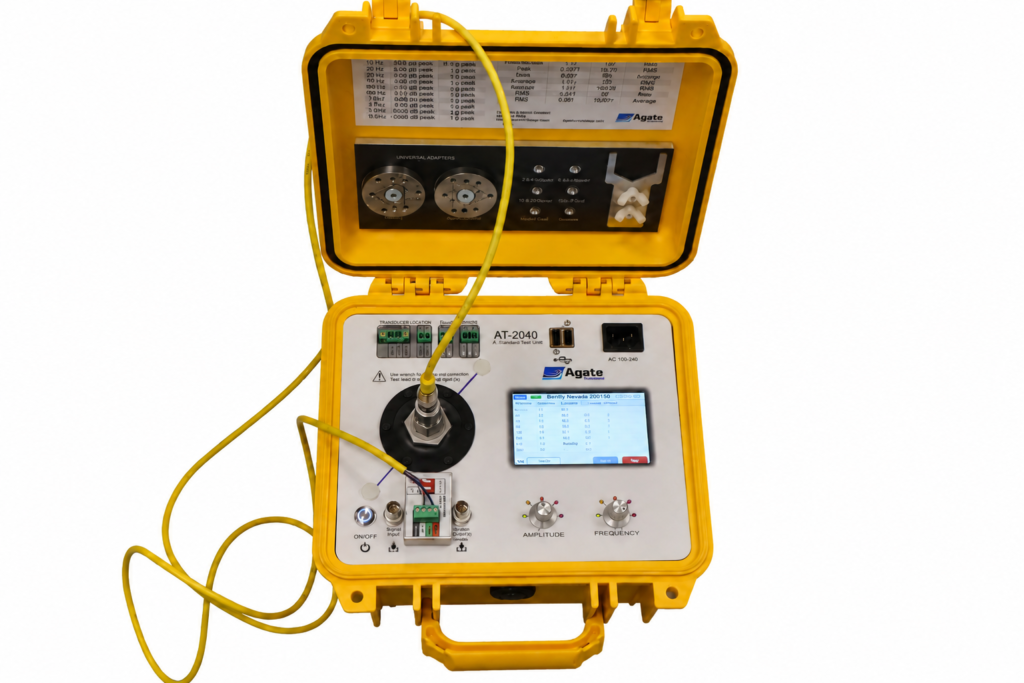
Test differential 5 V powered accelerometers using the AT-2040 and MEMS-100 adapter.

The Bently Nevada 200150 is different from a typical IEPE accelerometer. Instead of a standard single-ended IEPE signal, the 200150 uses 5 V excitation and a differential SIG+ / SIG- output.

The AT-2040 supports this application using the MEMS-100 adapter, allowing the sensor to be powered, read, and tested under controlled vibration from the AT-2040 shaker. The 200150 should be tested through the MEMS-100 adapter, not as a normal IEPE accelerometer and not through the negative-voltage proximity probe input..

Calibration of Bently Nevada 200150

200150 Sensor Summary

Typical application-note values include 100 mV/g sensitivity at 80 Hz, 10 to 1000 Hz frequency range, ±25 g measurement range, 4.7 to 5.5 Vdc excitation, less than 800 µA quiescent current, differential SIG+ / SIG- output, and approximately 2.5 Vdc output bias.

Differential Signal Input Through the MEMS-100 Adapter

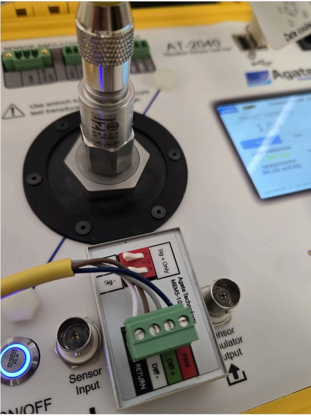
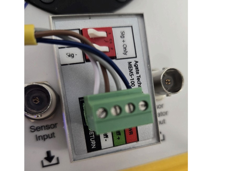
The MEMS-100 adapter provides the correct connection path for the 200150. The adapter powers the sensor at 5 V and accepts the differential signal pair through Diff+ and Diff-. Your installation note specifically states that the 200150 is a differential, 5 V powered accelerometer, so the AT-2040 needs the MEMS-100 interface adapter to power and read it.

Bently Nevada 200150

Eaton CSA55A5CY2202 Wiring Reference

Eaton Pin Wire Color Function MEMS-100 Terminal
1 Brown Differential Signal Diff−
2 Blue Sensor Power +PWR
3 Gray Differential Signal Diff+
4 Black Shield / Drain Not connected
5 White Return / Power −RETURN

Built-In 200150 Sensor Test Setup

The AT-2040 can be configured with a saved 200150 test profile. Once loaded, the sensor can be selected from Sensor Test → Bently Nevada → 200150, allowing technicians to run the same repeatable test points without manually rebuilding the setup each time.

Test Configuration

FieldValue
Sensor TypeMEMS_1X
Unitsg
Amplitude ModePeak
Voltage Out5.0 V
Reference Frequency80 Hz
Reference Amplitude1.0 g

Automatic Test Points

FrequencyAmplitude
20 Hz1.0 g
50 Hz1.0 g
80 Hz1.0 g
150 Hz1.0 g
200 Hz1.0 g
500 Hz1.0 g
1000 Hz1.0 g

How the AT-2040 Tests the 200150

Mount the sensor

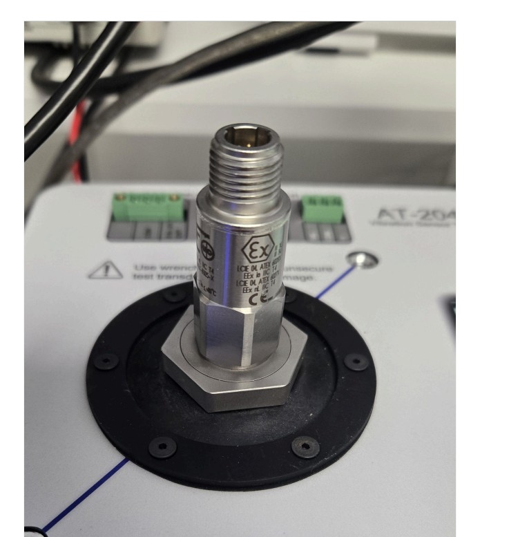
Install the 3/8-24 mounting stud and mount the 200150 to the AT-2040 shaker table. The installation note states that the 200150 has a 3/8-24 threaded hole and should be tightened using the stud or sensor hex flats, not by applying torque through the sensor body.
Connect through MEMS-100

Connect the 5-pin cable to the sensor and land the sensor wiring into the MEMS-100 adapter. The adapter should be set to SIG+ / SIG- differential mode for the 200150.
Bently Nevada 200150

Run the saved test profile

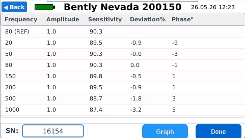
Select Sensor Test → Bently Nevada → 200150. The imported setup should show the 80 Hz reference row and seven test points: 20, 50, 80, 150, 200, 500, and 1000 Hz at 1.0 g.
Review and export results

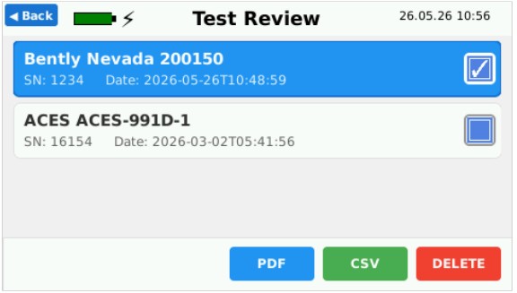
The AT-2040 fills in sensitivity, deviation, and phase as the sweep runs. Results are saved to the report database and can be exported as PDF or CSV. The autotest note shows the AT-2040 reporting sensitivity and deviation for each test point and then saving the result for report export.
Single-Point Live Verification

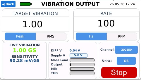
For quick functional checks, the AT-2040 can drive the shaker at a single frequency and amplitude while reading the 200150 through the MEMS-100 adapter. A common check is 80 Hz at 1.0 g peak with the channel set to MEMS 1X.


At this point, the expected sensor output is approximately 100 mV/g, with the differential bias near 2.5 V.

Bently Nevada and Trendmaster are trademarks or registered trademarks of Baker Hughes. Agate Technology is not affiliated with, sponsored by, or endorsed by Baker Hughes or Bently Nevada. Product names and model numbers are used only to identify sensor compatibility and application use.

Agate Tech logo

All rights reserved @2026

Follow Us On

Scroll to Top